The pictures dictate overview of assembly in no way am I liable for your outcome. ok?
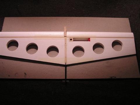
Draw reference lines at this time..one down the center of the 11 1/2" section and one 2 7/8 from the front this is where the 4 1/4 fillers will be glued and lastly one 4 1/2 in from the back of the blank this line will intersect the center line already drawn.....ok glue the fillers on now like in the picture. Next cut the taper on them to the contour of the wing root. Nice jig huh?
Now glue the nose block into place the 1/4 x 1 3/16 x 2 7/8" while that dries round over top of motor mount parts not where the motor sits leave that square...glue them onto the nose block making sure to have a 3/8" space between the engine mounts and the tapered fillers this is where the wing spar will reside..lets do some drilling now...........
I use a 9/64 drill for the bellcrank put it where you like or 1 7/8 behind the spar........
two 3/16 holes through the motor mounts and the rib not the filler 1/2 and 1 3/4 from front for 3/16 dowels. Drill the four 1/8 motor mount holes now...real hard once the model is together!
Big hole in the picture is a 27/64 on the intersecting line towards the rear of the rib this will be where the boom is located before this hole is drilled.. decide what you want for a boom this is for a carbon fiber boom you should have bought while you were in Texas getting motor mount stock hahahaahah well any way the ones I use are .414 diameter or is it .411? humm
when that is decided draw connecting lines to cut out with a band saw or something kinda like what's in the picture. Just be sure the boom fits in there and it is square. Those lines do help a lot!!!! Now for the boom and stabilator.............................................Ken
Ken Hargreaves Shows us how He Builds his Coyotes
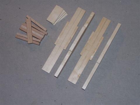
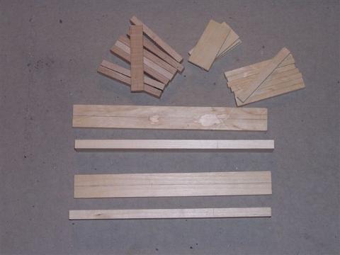
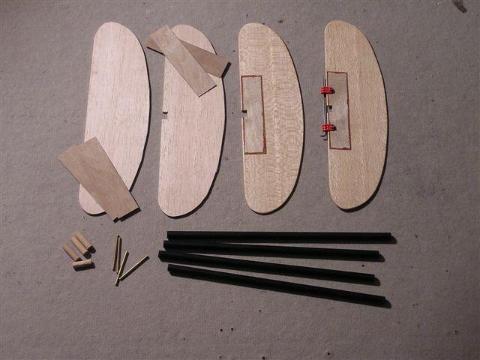
Here is all the components, already cut to size, that are needed to build four center ribs
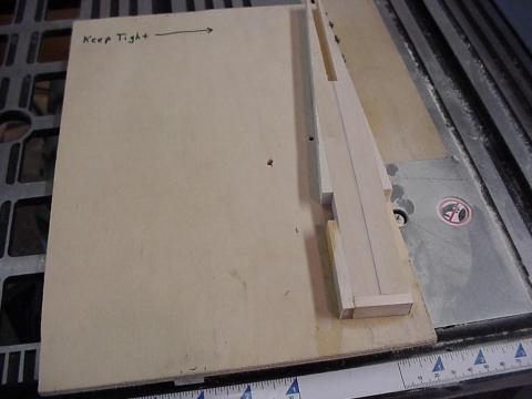
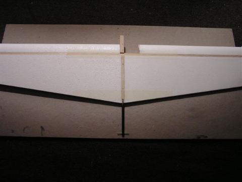
In this photo Ken has attached the small filler pieces that form the tapered section of the center rib just aft of the spars
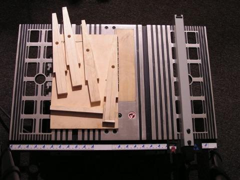
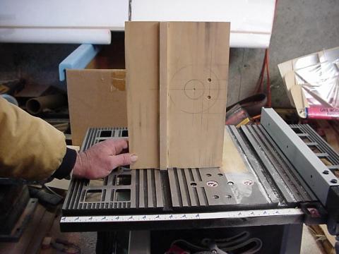
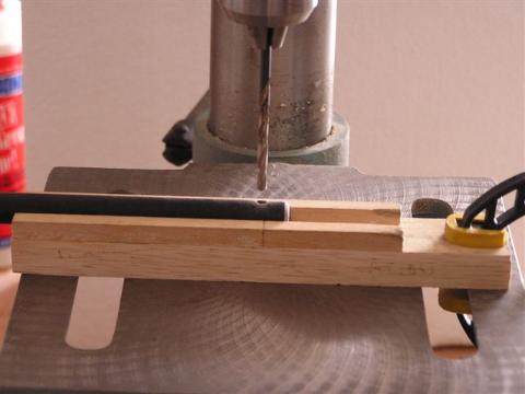
This photo shows all four center ribs with the aforementioned tapered section already cut - the fourth center rib is still sitting in the jig that allows Ken to use the side guide slot to cut this tapered section on his table saw. Notice that the hole that forms the end of the boom slot has also been drilled.
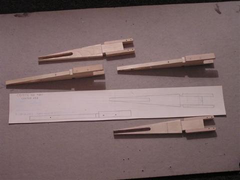
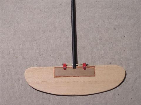
The completed assemblies - Ken does nice work
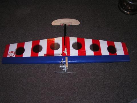
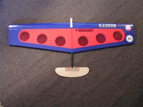
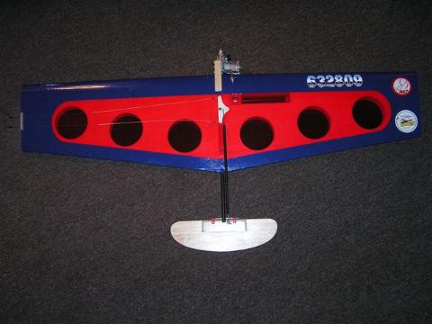
Here a photo of Ken's Patriot Coyote - The Editor's Favorite
Close up of Ken's center rib jig
bottom of jig showing projection that fits in the side guide slot
Boom & Stab
Make the boom a bit long until you know where you like your c.g. to be
start with 12"boom, cut a piece of wood dowel 1" long and fit it into the rear of the boom
glue it into place....drill a 1/8" hole 3/8" from the end and drill it through the dowel
this is the hinge point that the 2" piece of 1/8" brass tube will be glued in
I make the stab out of 1/8 x 4" balsa I found that this style of stab gives me
more stability........use whatever you prefer the doublers on the stab are needed
for strength and solid mounting of the Russian hinges and control horn
these are made of 1/64 ply...1 1/4" x 5" cut the notch for the boom in the stab
before gluing these on it will make cutting the doublers easier 3/32 music wire
is needed for attachment to hinges. fuel proof the finished stabs now
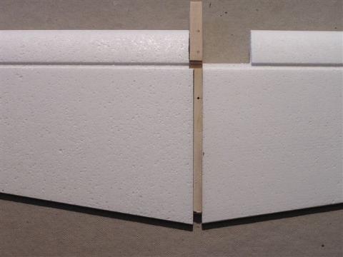
Prepare the wing cores
Shown in the pix there is a setup for hard tank and bladder compartment
these finished center ribs work with either set up. I use 3/4 oz tip weight
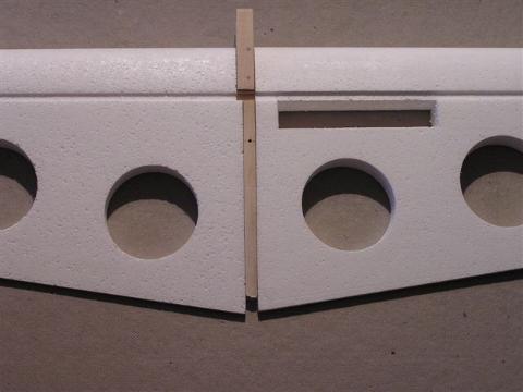
the tank cutout is 2 7/8" from root towards the out board side....see the pix?
I like to put the lead out guide behind the balsa wing tip..oh ya cut out some
1/8" balsa wing tip pieces...... just trace around one and copy that one
my lead out is located so that the forward hole is 1 5/8" behind the spar
the only other cut out is where the inboard wing attaches to the center rib
this is about 1/4" and it extends just under the wing spars for strength
give the wing cores a light sanding
OK now the assembly but first Thank you to Jim Carpenter for the Yankee Nipper
his construction ideas are incorporated into the Carbon Coyote that makes both models some of the very best there is in New England today.........Ken
Assembly
Add a filler piece on center rib to get the spar level with the wing surface
I use contact cement to glue wings and balsa tips together
this is kinda like combat"touch it once and your stuck good!"
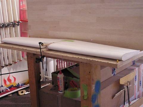
In the pix you can see how I set things up to get a nice flat model With the contact cement you must put the wings into position before
clamping down on work surface. I use short pieces of spar material to line
them up and carefully slip them onto the center rib.
Make sure the spars fit into the notches in the wing cores
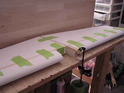
Glue them into place ( use Weldbond Glue ) and hold secure using masking tape
Put a piece of tape across the trail edge to hold that together for now,
I have had the spars pull open the trail edge before
Dry fit the stab assembly along with the engine and tank and push rod
you now set the c.g. where you want it by shortening the boom
My models have 5 3/8" from the trail edge to the front of the hinge tube
cant change this once it is glued in place so you might want to set it
up like your best flying model and finish this one to test it out
once you got it write the measurements down and build the all the same
I use 12 min epoxy and some micro balloons to glue the boom in
OK is it parallel?square? sets up kinda quick so don't mess around!!
Once dry drill a 1/8" hole through the rib and boom and pin it in
with a 1/8" dowel. Now fill in around the boom with scrap whatever
and if using a hard tank fill in around cut out with 1/8" balsa
When all this stuff is done take off all the masking tape and have a look
Wow not looking too bad huh!? Build a few and you will see how easy it is!!!
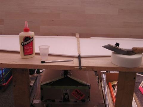
In this photo the boom assembly is glued in and Ken has the glue, tape and heat gun ready to apply the drywall tape
Fiber glass drywall tape time
This is crucial the bulk of the strength is in this tape!!Trust me I have pulled
many models out of the dirt with nothing more than a dirty engine to clean!!!
2@ 21" x 2" goes over the spar on lead edge
2@18" x 2" goes over the trail edge section
Very easy to see where in the pictures. I use a little(low) heat from a
mono cote iron to hold the tape down while gluing it to the wings
Tite Bond thinned 60/40 holds the tape down really good
When all this is dry sand the wings with fine paper and shape the tips
I am pretty sure the model should be built now and time to cover it.
Don't worry about fuel proofing the nose block I do that after covering it
The previous two photos show the hard tank and bladder tanked "Coyotes" with drywall tape applied.
Next (well after my solar film order comes from Horizon Hobbies) there will be some covering going on. What color is this one?
Note: there is a 1/4" x1/4" strip under each wing tip to keep things square and straight
Finishing the model
Hey what's this in the box of scrap? Red and blue that will do hahaha
Nothing from Horizon Hobbies yet..probably Tuesday,ok I like to
put a small bead of Weld Bond glue around the motor mount block
then fuel proof the nose. Seems to keep the covering down better
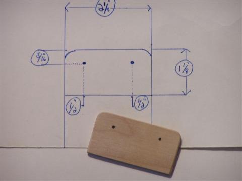
I make the lead out guide from 1/8" ply this is the one I use
use what you like,the .027 braided lead out wires are attached to the
bell crank now,make sure to leave enough wire to make up the other end, install the control horn now. I use the fiber glass push rod system make the rod 10" long and the 1/16" music wire will be bent to the proper length
First bend the bell crank side being sure that it clears the bell crank
then set up the controls dead neutral and put a couple pins in the
bell crank to hold it in this position mark the other 1/16" music wire
at the control horn this is critical !!! Make sure it is neutral !!!
If you haven't installed the lead out guide do so now
The other end of the lead outs can be made up now,here is how
Put both lead out wires thru the guide and slip a crimp onto the
DOWN LINE and pull the up line until the down line crimp touches the
lead out guide this is where the down line is crimped on
Make sure the crimps here are very strong!!!
Now the up line,set the bell crank in neutral and pin it into place
The up line is simple just make it the same length as the down line
If the push rod was set up neutral,your all set!!!
Safety is important but to loose a model by skimping here is crazy!!!
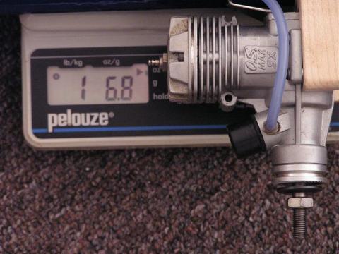
Well this one is right around the finish weight I look for but it might
need a little diet.OK put it in the rack and build another one!!!!
If you want Ken can be reached at Mill560@aol.com
Happy building and hope to see you in 2006!!!!
All Covered - Looking Good.
Leadout Guide Detail
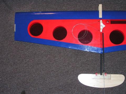
Bellcrank, Leadouts and Pushrod Detail
Engine Mounted
Weighing in at 1 lb 6.8 ounces - Ready for the first test flight